When designing steam cs seamless pipe in chemical plants, in order to ensure the quality and efficiency of the design, the pipe layout should meet the stress requirements. In addition, attention should be paid to other details. problem and avoid water hammer.
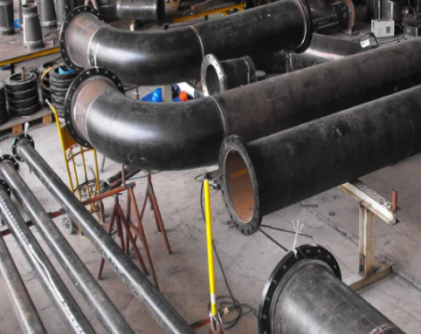
1. Design of steam cs seamless pipe
Many different pipelines are installed in chemical equipment. They are generally arranged outside the factory building or along the equipment, and are supported in the air with brackets to form a pipe gallery. There are specific requirements for the configuration of the pipe gallery. Generally, process material pipes are arranged on the first floor and the first floor pipe gallery, utility pipes are arranged on the third floor, and instrument cable trough plates are arranged on the fourth floor. The steam cs seamless pipe are arranged on the third layer.
In order to facilitate the installation of π-shaped compensator, generally steam cs seamless pipe should be arranged on the front side of the pipe gallery. At high temperatures, steam cs seamless pipe will expand. At this time, a π-shaped compensator can be used to absorb the thermal expansion of the pipes. Since bellows expansion joints are relatively expensive and have a short service life, they are generally not used to absorb the thermal expansion of steam cs seamless pipe.

When determining the installation location of the compensator, the pipeline must first be strictly analyzed so that the compensator can be set centrally. The pipes with relatively high temperatures and large compensation amounts are generally installed on the outside, while the corresponding pipes with lower temperatures and smaller compensation amounts are installed on the inner side.
The π-shaped compensator is generally set in the middle position, and guide frames are set on both sides of the compensator. The distance between the guide frame and the compensator is determined according to the stress of the pipe.
When calculating the thrust of the bracket and the stress of the steam cs seamless pipe, the stress of the entire steam cs seamless pipe must be calculated. Generally, multi-layer pipe galleries are installed in chemical plants, and steam cs seamless pipe are installed on the upper layer of the multi-layer pipe gallery, so that low-temperature pipes and liquid hydrocarbon pipes are not adjacent.
On the same layer, steam cs seamless pipe and electronic instrument cables can be arranged at the same time, but the distance between them must be ensured not to be less than 200mm. Steam cs seamless pipe can also be arranged in the lower layer of electronic instrument cables, but the spacing cannot be less than 500mm.
2. Design of steam cs seamless pipe drainage facilities
Under normal circumstances, special drainage is set up in the steam cs seamless pipe in the warm pipe stage. Because a large amount of condensation will be generated when driving, special drainage facilities must be set up. The setting of the drainage facilities should be selected according to the different levels of steam pressure.
Ultra-high-pressure pipelines do not produce condensate under normal circumstances, and there are no condensate pipelines of corresponding specifications installed on ultra-high-pressure steam ducts, so hydrophobic facilities are generally not installed on ultra-high-pressure ducts. Ultra-high pressure pipelines have the characteristics of thick wall, difficulty in opening holes, and high pressure, so they generally do not have a liquid separation bag.
Under normal circumstances, condensate will not generally occur in high-pressure, medium-pressure and low-pressure pipelines. However, in order to prevent steam cs seamless pipe from producing a large amount of condensate during the pipe heating stage or startup stage, it is necessary to Set drain valves, liquid separation bags and other hydrophobic facilities on these steam cs seamless pipe.
When setting up the drainage facilities of the steam cs seamless pipe pipeline, the liquid separation bag should be set at the end of the steam main pipe. The interval between the liquid separation bags on the steam main pipe also has certain regulations. If it is in a saturated state, The distance between the dispensing bags in the device is 80mm.
If overheated, the spacing between dispenser bags should be 160mm. If the device is running along a slope, the distance between the liquid separation bags outside the device should be 300mkm. If the device is running against a slope, the distance between the liquid separation bags outside the device should be 200mm. The steam diverter is generally installed when the saturated steam main pipe enters the device, and should be installed near the boundary of the device side. In addition, regular drainage measures should be installed at the lower part of the water distributor.
If the superheated steam pipe enters the device, there is no need to set up a water distributor. The steam vent pipe should be discharged directly to the atmosphere, so a drainage hole should be opened at the lower end of the steam vent pipe, and a DN15 pipe should be connected to a suitable place such as a drainage ditch or funnel. Guide and load-bearing brackets should also be provided on the steam vent pipe. Because pan steam piping often discharges or is connected to discharge, it should be directed to the main operating area or a place where there are not many operators.
3. Design of steam branch pipes
There is a steam branch pipe installed on the top of the steam main pipe. Generally, a cut-off valve is installed on the steam branch pipe. In order to avoid liquid accumulation, the cut-off valve should be set on the horizontal pipe, close to the main pipe. Some steam cs seamless pipe have strict steam requirements, so steam branch pipes cannot be connected to such steam cs seamless pipe. In addition, the branch pipes cannot be connected from the π-shaped compensator of the steam cs seamless pipe. Take it out.
If the branch pipe is connected to the main pipe at both ends of the π-shaped compensator, the branch pipe should not be affected by the displacement of the steam main pipe. During thermal expansion, the steam main pipe will cause displacement of the outlet point of the branch pipe, and the branch pipe will not bear excessive pressure or excessive displacement.
Under normal circumstances, when the branch pipe is connected to the steam main pipe, a two-valve group is used. However, in order to allow leakage to be discovered at any time, the two-valve group cannot be used to lead from the steam branch pipe or the steam main pipe to other parts. On the process pipeline, a three-valve group should be installed. Depending on the situation, the drainage settings, such as drain valves or traps, should be set at the low point of the steam branch pipe. When setting up drainage facilities on the official road, the different pressure levels on the pipe corridor should be used.
4. Design of steam-condensate pipelines
Generally, steam cs seamless pipe and steam condensate pipes are arranged on the same floor in the pipe gallery. In order to prevent water hammer, π-shaped compensators can be installed on the steam condensate pipes. This kind of π-row compensator should be set in a horizontal direction, or the riser should be designed as an inclined section.
Condensate comes out of steam traps with different pressures and should be connected to their respective recovery main pipes. When the nominal diameter of the branch pipe is not less than 50mm, it can be directly connected to the top of the steam condensate recovery main pipe. The printing plate uses a flange connection as a trap set in the steam condensate recovery system, and there should be no bag shape on the pipe at the trap inlet.
If the trap is lower than the steam and condensate recovery main, a check valve should also be installed behind the trap. When installing the check valve, it should be installed on the horizontal pipe, close to the steam and condensate main pipe. The check valve should also be connected with a flange, which can facilitate the purging and disassembly of the steam cs seamless pipe pipeline.
1. Design of steam cs seamless pipe
Many different pipelines are installed in chemical equipment. They are generally arranged outside the factory building or along the equipment, and are supported in the air with brackets to form a pipe gallery. There are specific requirements for the configuration of the pipe gallery. Generally, process material pipes are arranged on the first floor and the first floor pipe gallery, utility pipes are arranged on the third floor, and instrument cable trough plates are arranged on the fourth floor. The steam cs seamless pipe are arranged on the third layer.
In order to facilitate the installation of π-shaped compensator, generally steam cs seamless pipe should be arranged on the front side of the pipe gallery. At high temperatures, steam cs seamless pipe will expand. At this time, a π-shaped compensator can be used to absorb the thermal expansion of the pipes. Since bellows expansion joints are relatively expensive and have a short service life, they are generally not used to absorb the thermal expansion of steam cs seamless pipe.
When determining the installation location of the compensator, the pipeline must first be strictly analyzed so that the compensator can be set centrally. The pipes with relatively high temperatures and large compensation amounts are generally installed on the outside, while the corresponding pipes with lower temperatures and smaller compensation amounts are installed on the inner side.
The π-shaped compensator is generally set in the middle position, and guide frames are set on both sides of the compensator. The distance between the guide frame and the compensator is determined according to the stress of the pipe.
When calculating the thrust of the bracket and the stress of the steam cs seamless pipe, the stress of the entire steam cs seamless pipe must be calculated. Generally, multi-layer pipe galleries are installed in chemical plants, and steam cs seamless pipe are installed on the upper layer of the multi-layer pipe gallery, so that low-temperature pipes and liquid hydrocarbon pipes are not adjacent.
On the same layer, steam cs seamless pipe and electronic instrument cables can be arranged at the same time, but the distance between them must be ensured not to be less than 200mm. Steam cs seamless pipe can also be arranged in the lower layer of electronic instrument cables, but the spacing cannot be less than 500mm.
2. Design of steam cs seamless pipe drainage facilities
Under normal circumstances, special drainage is set up in the steam cs seamless pipe in the warm pipe stage. Because a large amount of condensation will be generated when driving, special drainage facilities must be set up. The setting of the drainage facilities should be selected according to the different levels of steam pressure.
Ultra-high-pressure pipelines do not produce condensate under normal circumstances, and there are no condensate pipelines of corresponding specifications installed on ultra-high-pressure steam ducts, so hydrophobic facilities are generally not installed on ultra-high-pressure ducts. Ultra-high pressure pipelines have the characteristics of thick wall, difficulty in opening holes, and high pressure, so they generally do not have a liquid separation bag.
Under normal circumstances, condensate will not generally occur in high-pressure, medium-pressure and low-pressure pipelines. However, in order to prevent steam cs seamless pipe from producing a large amount of condensate during the pipe heating stage or startup stage, it is necessary to Set drain valves, liquid separation bags and other hydrophobic facilities on these steam cs seamless pipe.
When setting up the drainage facilities of the steam cs seamless pipe pipeline, the liquid separation bag should be set at the end of the steam main pipe. The interval between the liquid separation bags on the steam main pipe also has certain regulations. If it is in a saturated state, The distance between the dispensing bags in the device is 80mm.
If overheated, the spacing between dispenser bags should be 160mm. If the device is running along a slope, the distance between the liquid separation bags outside the device should be 300mkm. If the device is running against a slope, the distance between the liquid separation bags outside the device should be 200mm. The steam diverter is generally installed when the saturated steam main pipe enters the device, and should be installed near the boundary of the device side. In addition, regular drainage measures should be installed at the lower part of the water distributor.
If the superheated steam pipe enters the device, there is no need to set up a water distributor. The steam vent pipe should be discharged directly to the atmosphere, so a drainage hole should be opened at the lower end of the steam vent pipe, and a DN15 pipe should be connected to a suitable place such as a drainage ditch or funnel. Guide and load-bearing brackets should also be provided on the steam vent pipe. Because pan steam piping often discharges or is connected to discharge, it should be directed to the main operating area or a place where there are not many operators.
3. Design of steam branch pipes
There is a steam branch pipe installed on the top of the steam main pipe. Generally, a cut-off valve is installed on the steam branch pipe. In order to avoid liquid accumulation, the cut-off valve should be set on the horizontal pipe, close to the main pipe. Some steam cs seamless pipe have strict steam requirements, so steam branch pipes cannot be connected to such steam cs seamless pipe. In addition, the branch pipes cannot be connected from the π-shaped compensator of the steam cs seamless pipe. Take it out.
If the branch pipe is connected to the main pipe at both ends of the π-shaped compensator, the branch pipe should not be affected by the displacement of the steam main pipe. During thermal expansion, the steam main pipe will cause displacement of the outlet point of the branch pipe, and the branch pipe will not bear excessive pressure or excessive displacement.
Under normal circumstances, when the branch pipe is connected to the steam main pipe, a two-valve group is used. However, in order to allow leakage to be discovered at any time, the two-valve group cannot be used to lead from the steam branch pipe or the steam main pipe to other parts. On the process pipeline, a three-valve group should be installed. Depending on the situation, the drainage settings, such as drain valves or traps, should be set at the low point of the steam branch pipe. When setting up drainage facilities on the official road, the different pressure levels on the pipe corridor should be used.
4. Design of steam-condensate pipelines
Generally, steam cs seamless pipe and steam condensate pipes are arranged on the same floor in the pipe gallery. In order to prevent water hammer, π-shaped compensators can be installed on the steam condensate pipes. This kind of π-row compensator should be set in a horizontal direction, or the riser should be designed as an inclined section.
Condensate comes out of steam traps with different pressures and should be connected to their respective recovery main pipes. When the nominal diameter of the branch pipe is not less than 50mm, it can be directly connected to the top of the steam condensate recovery main pipe. The printing plate uses a flange connection as a trap set in the steam condensate recovery system, and there should be no bag shape on the pipe at the trap inlet.
If the trap is lower than the steam and condensate recovery main, a check valve should also be installed behind the trap. When installing the check valve, it should be installed on the horizontal pipe, close to the steam and condensate main pipe. The check valve should also be connected with a flange, which can facilitate the purging and disassembly of the steam cs seamless pipe pipeline.