Carbon Steel Pipe
Stainless Steel Pipe
Fittings
OCTG
Steel Structure
Value-Added Products
Clad Pipe
Coated Steel Pipe
Technical Data
Photos
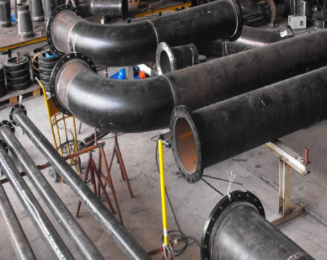
Drill Pipe, Heavy Weight Drill Pipe, Drill Collar
Size: 2-3/8"--6-5/8"
Standard: API 5DP
Grade: E75, G105, S135, SS-105, X95, X57, X75, X39
Length: Range 1, Range 2, Range 3
| Drill pipe diameter | Drill pipe ID | Drill pipe weight |
| 2-3/8 inch | 1.815 inch | 6.65 lb/ft |
| 2-7/8 inch | 2.151 inch | 10.40 lb/ft |
| 3-1/2 inch | 2.764 inch, 2.602 inch | 13.30 lb/ft, 15.50 lb/ft |
| 4 inch | 3.340 inch, 3.240 inch | 14.00 lb/ft, 15.70 lb/ft |
| 4-1/2 inch | 3.826 inch, 3.640 inch | 16.60 lb/ft, 20 lb/ft |
| 5 inch | 4.726 inch, 4.000 inch | 19.50 lb/ft, 25.60 lb/ft |
| 5-1/2 inch | 4.778 inch, 4.670 inch | 21.90 lb/ft, 24.70 lb/ft |
| 6-5/8 inch | 5.965 inch, 5.901 inch | 25.20 lb/ft, 27.70 lb/ft |
Upset of Drill Pipe
Internal Upset IU
External Upset EU
Internal-External Upset IEU
Thread/Connection Types of Drill Pipe
NC26, NC31, NC38, NC40, NC46, NC50, 5-1/2 FH, 6-5/8 FH
XT Connection of Drill Pipe
XT connections facilitate the use of larger drill pipe in a set hole size, such as 5⅞ in. drill pipe with XT 57 in an 8½ in. hole size.
X57, X75, X39
|
Mechanical properties of API drill pipe grades |
||||
|
Grade
|
Yield strength
|
Tensile strength
|
API
|
|
|
psi
N/mm2
min.
|
psi
N/mm2
max.
|
psi
N/mm2
min.
|
||
| E-75 |
75 000
515
|
105 000
725
|
100 000
690
|
Spec. 5 DP
|
| X-95 |
95 000
655
|
125 000
860
|
105 000
725
|
Spec. 5 DP
|
| G-105 |
105 000
725
|
135 000
930
|
115 000
795
|
Spec. 5 DP
|
| S-135 |
135 000
930
|
165 000
1 140
|
145 000
1 000
|
Spec. 5 DP
|
|
Mechanical properties of API tool joint grades |
||||
|
Yield strength
|
Yield strength
|
Tensile strength
|
Elongation
|
Box
|
|
psi
N/mm2
min.
|
psi
N/mm2
max
|
psi
N/mm2
min
|
in 2 inches
%
min
|
Hardness
Brinell
min
|
|
120 000
827
|
165 000
1138
|
140 000
965
|
13 | 285 |
|
Chemical composition requirements |
||||
| Pipe body |
Phosphorus
max. %
|
Sulfur
max. %
|
||
|
Pipe body grade E
|
0.030
|
0.020
|
||
|
Pipe body grades X, G and S
|
0.020
|
0.015
|
||
|
Tool joint
|
0.020 |
0.015
|
||
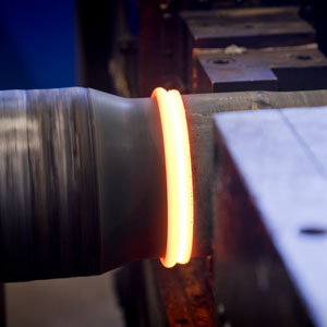
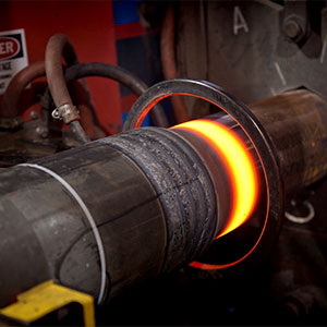
Details of manufacturing

Tool joints are inertia welded to the tubes with computer-monitored precision. Concentricity is carefully monitored and controlled, and the parameters of each weld are electronically recorded, and traceable to each joint.
After removal of weld flash, the weld area is austenitized, quenched, and tempered to achieve the required mechanical properties. Heat treat cycles for each weld are compared to specific parameters and recorded for traceability.
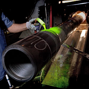
After all steps and machine marks are polished from the OD and ID area, hardness testing, ultrasonic testing, and wet magnetic particle inspections are used to verify the integrity of each weld zone.
Drill-pipe corrosion
Drill-pipe corrosion is a critical issue for any drilling operation, particularly under high-pressure, high-temperature downhole conditions. However, most laboratory studies have been conducted under ambient and static conditions, with only a few downhole studies based on flow loop showing inconsistent results. In this study, we proposed a novel simple method to simulate pipe corrosion/erosion in a reservoir-like environment under both the static and dynamic conditions and investigated the influences of wellbore conditions, including temperature, pressure and salinity of water-based drilling fluids, on the corrosion behaviour of the drill pipe. The results showed that the erosion effect of the drilling fluid (without drilled cuttings) was negligible. Furthermore, we found that the corrosion rate increased with an increase in the temperature, pressure and rotational speed; however, it decreased with an increase in the salinity. In addition, the proposed method can be used to simulate other complicated conditions.

Drill Pipe Dimensional Range and Performance Properties
|
Pipe Figures |
||||||||||
|
Plant |
NominalSize |
NominalWeight |
Wallthickness |
InsideDiameter |
Grade |
Upset |
TensileYield |
TorsionalYield |
InternalPressure |
Collapse |
|
in |
lb/ft |
in |
in |
lb |
ft-lb |
psi |
psi |
|||
|
mm |
kg/m |
mm |
mm |
kN |
Nm |
bar |
bar |
|||
|
3 |
2 3/8 60,3 |
6.65 9,34 |
0.280 7,11 |
1.815 46,13 |
E75 |
EU |
138 214 615 |
6 250 8 474 |
15 474 1 067 |
15 599 1 075 |
|
6.65 9,34 |
0.280 7,11 |
1.815 46,13 |
Х95 |
EU |
175 072 779 |
7 917 10 734 |
19 600 1 351 |
19 759 1 362 |
||
|
6.65 9,34 |
0.280 7,11 |
1.815 46,13 |
G105 |
EU |
193 500 861 |
8 751 11 864 |
21 663 1 493 |
21 839 1 505 |
||
|
3 |
2 7/8 73,0 |
10.4 15,49 |
0.362 9,19 |
2.151 54,64 |
E75 |
EU |
214 344 953 |
11 554 15 665 |
16 526 1 139 |
16 509 1 138 |
|
10.4 15,49 |
0.362 9,19 |
2.151 54,64 |
Х95 |
EU |
271 503 1208 |
14 635 19 842 |
20 933 1 443 |
20 911 1 441 |
||
|
10.4 15,49 |
0.362 9,19 |
2.151 54,64 |
G105 |
EU |
300 082 1335 |
16 176 21 932 |
23 137 1 595 |
23 112 1 593 |
||
|
10.4 15,49 |
0.362 9,19 |
2.151 54,64 |
S135 |
EU |
385 820 1716 |
20 798 28 198 |
29 747 2 051 |
29 716 2 048 |
||
|
3 |
3 1/2 88,9 |
13.3 19,81 |
0.368 9,35 |
2.764 70,20 |
E75 |
EU |
271 569 1208 |
18 551 25 152 |
13 800 951 |
14 113 973 |
|
13.3 19,81 |
0.368 9,35 |
2.764 70,20 |
Х95 |
EU |
343 988 1530 |
23 498 31860 |
17 480 1 205 |
17 877 1 232 |
||
|
13.3 19,81 |
0.368 9,35 |
2.764 70,20 |
G105 |
EU |
380 197 1691 |
25 972 35213 |
19 320 1 332 |
19 758 1 362 |
||
|
13.3 19,81 |
0.368 9,35 |
2.764 70,20 |
S135 |
EU |
488 825 2174 |
33 392 45 273 |
24 840 1 712 |
25 404 1 751 |
||
|
15.5 23,09 |
0.449 11,4 |
2.602 66,10 |
E75 |
EU |
322 775 1436 |
21 086 28 589 |
16 838 1 160 |
16 774 1 156 |
||
|
15.5 23,09 |
0.449 11,4 |
2.602 66,10 |
Х95 |
EU |
408 848 1819 |
26 708 36 211 |
21 328 1 470 |
21 247 1 465 |
||
|
15.5 23,09 |
0.449 11,4 |
2.602 66,10 |
G105 |
EU |
451 885 2010 |
29 520 40 023 |
23 573 1 625 |
23 484 1 619 |
||
|
15.5 23,09 |
0.449 11,4 |
2.602 66,10 |
S135 |
EU |
580 995 2585 |
37 954 51 459 |
30 308 2 090 |
30 194 2 081 |
||
|
3 |
4 101,6 |
14.0 20,85 |
0.330 8,38 |
3.340 84,84 |
E75 |
IU |
258 359 1269 |
23 288 31574 |
10 828 746 |
11 354 782 |
|
14.0 20,85 |
0.330 8,38 |
3.340 84,84 |
Х95 |
IU |
361 454 1608 |
29 498 39 994 |
13 716 945 |
14 382 992 |
||
|
14.0 20,85 |
0.330 8,38 |
3.340 84,84 |
G105 |
IU |
399 502 1777 |
32 603 44 204 |
15 159 1 045 |
15 896 1 096 |
||
|
Tool Joint Figures |
Assembly |
||||||||
|
Connection |
OutsideDiameter |
InsideDiameter |
TongLengthPin |
TongLengthBox |
TensileYield |
TorsionalYield |
Aprox. Weight |
TorsionalRatio, pinto pipe |
Make-uptorque |
|
in |
in |
in |
in |
lb |
ft-lb |
lb/ft |
ft-lb |
||
|
mm |
mm |
mm |
mm |
kN |
Nm |
kg/m |
Nm |
||
|
NC26 |
3 3/8 85,725 |
1 3/4 27,15 |
7 177,8 |
8 203,2 |
313 681 1 395 |
6 875 9 321 |
6.99 10,41 |
1.10 |
4 125 5 593 |
|
NC26 |
3 3/8 85,725 |
1 3/4 27,15 |
7 177,8 |
8 203,2 |
313 681 1 395 |
6 875 9 321 |
7.11 10,59 |
0.87 |
4 125 5 593 |
|
NC26 |
3 3/8 85,725 |
1 3/4 27,15 |
7 177,8 |
8 203,2 |
313 681 1 395 |
6 875 9 321 |
7.11 1059 |
0.79 |
4 125 5 593 |
|
NC31 |
4 1/8 104,8 |
2 1/8 53,98 |
7 177,8 |
9 228,6 |
447 130 1 989 |
11 790 15 985 |
10.87 16,19 |
1.02 |
7 122 9 656 |
|
NC31 |
4 1/8 104,8 |
2 50,80 |
7 177,8 |
9 228,6 |
495 726 2 205 |
13 158 17 839 |
11.09 16,52 |
0.90 |
7 918 10 735 |
|
NC31 |
4 1/8 104,8 |
2 50,80 |
7 177,8 |
9 228,6 |
495 726 2 205 |
13 158 17 839 |
11.09 16,52 |
0.81 |
7 918 10 735 |
|
NC31 |
4 3/8 111,1 |
1 5/8 41,28 |
7 177,8 |
9 228,6 |
623 844 2 775 |
16 809 22 790 |
11.55 17,20 |
0.81 |
10 167 13 785 |
|
NC38 |
4 3/4 120,7 |
2 11/16 68,26 |
8 203,2 |
10 1/2 266,7 |
587 308 2 613 |
18 071 24 500 |
13.93 20,75 |
0.97 |
10 864 14 730 |
|
NC38 |
5 127,0 |
2 9/16 65,09 |
8 203,2 |
10 1/2 266,7 |
649 158 2 888 |
20 095 27 245 |
14.62 21,78 |
0.86 |
12 196 16 536 |
|
NC38 |
5 127,0 |
2 7/16 61,91 |
8 203,2 |
10 1/2 266,7 |
708 063 3 150 |
22 035 29 875 |
14.71 21,91 |
0.85 |
13 328 18 070 |
|
NC38 |
5 127,0 |
2 1/8 53,98 |
8 203,2 |
10 1/2 266,7 |
842 440 3 748 |
26 503 35 933 |
14.92 22,22 |
0.79 |
15 909 21 570 |
|
NC38 |
5 127,0 |
2 9/16 65,09 |
8 203,2 |
10 1/2 266,7 |
649 158 2 888 |
20 095 27 245 |
16.54 24,64 |
0.95 |
12 196 16 536 |
|
NC38 |
5 127,0 |
2 7/16 61,91 |
8 203,2 |
10 1/2 266,7 |
708 063 3 150 |
22 035 29 875 |
16.82 25,05 |
0.86 |
13 328 18 070 |
|
NC38 |
5 127,0 |
2 1/8 53,98 |
8 203,2 |
10 1/2 266,7 |
842 440 3 748 |
26 503 35 933 |
17.03 25,37 |
0.90 |
15 909 21 570 |
|
NC40 |
5 1/2 139,7 |
2 1/4 57,15 |
7 177,8 |
10 254,0 |
979 996 4 360 |
32 693 44 325 |
17.57 26,17 |
0.86 |
19 766 26 799 |
|
NC40 |
5 1/4 133,4 |
2 13/16 71,44 |
7 177,8 |
10 254,0 |
711 611 3 166 |
23 279 31 562 |
15.04 22,40 |
1.00 |
17 092 19 106 |
|
NC40 |
5 1/4 133,4 |
2 11/16 68,26 |
7 177,8 |
10 254,0 |
776 406 3 454 |
25 531 34 615 |
15.34 22,85 |
0.87 |
15 404 20 885 |
|
NC40 |
5 1/2 139,7 |
2 7/16 61,91 |
7 177,8 |
10 254,0 |
897 161 3 991 |
29 764 40 354 |
15.91 23,70 |
0.91 |
18 068 24 497 |
|
Pipe Figures |
||||||||||
|
Plant |
NominalSize |
NominalWeight |
Wallthickness |
InsideDiameter |
Grade |
Upset |
TensileYield |
TorsionalYield |
InternalPressure |
Collapse |
|
in |
lb/ft |
in |
in |
lb |
ft-lb |
psi |
psi |
|||
|
mm |
kg/m |
mm |
mm |
kN |
Nm |
bar |
bar |
|||
|
4 |
4 1/2 114,3 |
16.6 24,73 |
0.337 8,56 |
3.826 97,18 |
E75 |
IEU |
330 558 1 470 |
30 807 41 774 |
9 829 678 |
10 392 717 |
|
16.6 24,73 |
0.337 8,56 |
3.826 97,18 |
X95 |
IEU |
418 707 1 863 |
39 022 52 914 |
12 450 859 |
12 765 880 |
||
|
16.6 24,73 |
0.337 8,56 |
3.826 97,18 |
G105 |
IEU |
462 781 2 059 |
43 130 58 484 |
13 761 949 |
13 825 953 |
||
|
16.6 24,73 |
0.337 8,56 |
3.826 97,18 |
S135 |
IEU |
595 004 2 647 |
55 453 75 194 |
17 693 1 220 |
16 773 1157 |
||
|
20.00 29,79 |
0.430 10,92 |
3.64 92,46 |
E75 |
IEU |
412 358 1 834 |
36 901 50 038 |
12 542 865 |
12 964 894 |
||
|
20.00 29,79 |
0.430 10,92 |
3.64 92,46 |
X95 |
IEU |
522 320 2 323 |
46 741 63 381 |
15 886 1 096 |
16 421 1132 |
||
|
20.00 29,79 |
0.430 10,92 |
3.64 92,46 |
G105 |
IEU |
577 301 2 568 |
51 661 70 052 |
17 558 1 211 |
18 149 1252 |
||
|
20.00 29,79 |
0.430 10,92 |
3.64 92,46 |
S135 |
IEU |
742 244 3 302 |
66 421 90 067 |
2 2575 1 557 |
23 335 1609 |
||
|
4 |
5 127,0 |
19.50 29,05 |
0.362 9,19 |
4.276 108,62 |
E75 |
IEU |
395 595 1 760 |
41 167 55 822 |
9 503 655 |
9 962 687 |
|
19.50 29,05 |
0.362 9,19 |
4.276 108,62 |
E75 |
IEU |
395 595 1 760 |
41 167 55 822 |
9 503 655 |
9 962 687 |
||
|
19.50 29,05 |
0.362 9,19 |
4.276 108,62 |
X95 |
IEU |
501 087 2 229 |
52 144 70 707 |
12 037 830 |
12 026 829 |
||
|
19.50 29,05 |
0.362 9,19 |
4.276 108,62 |
X95 |
IEU |
501 087 2 229 |
52 144 70 707 |
12 037 830 |
12 026 829 |
||
|
19.50 29,05 |
0.362 9,19 |
4.276 108,62 |
G105 |
IEU |
553 833 2 464 |
57 633 78 150 |
13 304 918 |
12 999 896 |
||
|
19.50 29,05 |
0.362 9,19 |
4.276 108,62 |
G105 |
IEU |
553 833 2 464 |
57 633 78 150 |
13 304 918 |
12 999 896 |
||
|
19.50 29,05 |
0.362 9,19 |
4.276 108,62 |
S135 |
IEU |
712 070 3 168 |
74 100 100 480 |
17 105 1180 |
15 672 1 081 |
||
|
19.50 29,05 |
0.362 9,19 |
4.276 108,62 |
S135 |
IEU |
712 070 3 168 |
74 100 100 480 |
17 105 1180 |
15 672 1 081 |
||
|
25.60 38,13 |
0.50 12,70 |
4.000 101,60 |
E75 |
IEU |
530 144 2 358 |
52 257 70 860 |
13 125 905 |
13 500 931 |
||
|
25.60 38,13 |
0.50 12,70 |
4.000 101,60 |
E75 |
IEU |
530 144 2 358 |
52 257 70 860 |
13 125 905 |
13500 931 |
||
|
Tool Joint Figures |
Assembly |
||||||||
|
Connection |
OutsideDiameter |
InsideDiameter |
TongLengthPin |
TongLengthBox |
TensileYield |
TorsionalYield |
Aprox. Weight |
TorsionalRatio, pinto pipe |
Make-uptorque |
|
in |
in |
in |
in |
lb |
ft-lb |
lb/ft |
ft-lb |
||
|
mm |
mm |
mm |
mm |
kN |
Nm |
kg/m |
Nm |
||
|
NC 46 |
6 1/4 158,8 |
3 1/4 82,55 |
7 177,8 |
10 254,0 |
901 164 4 009 |
33 228 45 057 |
18.37 27,35 |
1.09 |
20.396 27657 |
|
NC 46 |
6 1/4 158,8 |
3 76,20 |
7 177,8 |
10 254,0 |
1 048 426 4 664 |
38 998 52 881 |
18.79 27,98 |
1.01 |
20.396 27657 |
|
NC 46 |
6 1/4 158,8 |
3 76,20 |
7 177,8 |
10 254,0 |
1 048 426 4 664 |
38 998 52 881 |
18.79 27,98 |
0.91 |
23.795 32 266 |
|
NC 46 |
6 1/4 158,8 |
2 3/4 69,85 |
7 177,8 |
10 2 54,0 |
1 183 908 5 266 |
44 359 60 151 |
19.00 28,29 |
0.81 |
26.923 36 508 |
|
NC 46 |
6 1/4 158,75 |
3 76,20 |
7 177,8 |
10 254,0 |
1 048 426 4 664 |
38 998 52 881 |
22.09 32,89 |
1.07 |
23.795 32 266 |
|
NC 46 |
6 1/4 158,75 |
2 3/4 69,85 |
7 177,8 |
10 254,0 |
1 183 908 5 266 |
44 359 60 151 |
22.67 33,76 |
0.96 |
26.923 36 508 |
|
NC 46 |
6 1/4 158,75 |
2 1/2 63,50 |
7 177,8 |
10 254,0 |
1 307 608 5 817 |
49 297 66 847 |
22.86 34,03 |
0.96 |
29.778 40 379 |
|
NC 46 |
6 1/4 158,75 |
2 1/4 57,15 |
7 177,8 |
10 254,0 |
1 419 527 6 315 |
53 800 79 953 |
23.03 34,29 |
0.81 |
|
|
NC 50 |
6 5/8 168,28 |
3 3/4 95,25 |
7 177,8 |
10 254,0 |
939 095 4 177 |
37 269 50 537 |
20.85 31,05 |
0.92 |
22.836 30 966 |
|
51/2 FH |
7 177,8 |
3 3/4 95,25 |
8 203,2 |
10 254,0 |
1 448 407 6 443 |
62 903 85 296 |
22.28 33,17 |
1.53 |
|
|
NC 50 |
6 5/8 168,28 |
3 1/2 88,90 |
7 177,8 |
10 254,0 |
1 109 920 4 937 |
44 456 60 282 |
21.45 31,94 |
0.86 |
27.076 36 715 |
|
51/2 FH |
7 177,8 |
3 3/4 95,25 |
8 203,2 |
10 254,0 |
1 448 407 6 443 |
62 903 85 296 |
22.62 33,68 |
1.21 |
|
|
NC 50 |
6 5/8 168,28 |
3 1/4 82,55 |
7 177,8 |
10 254,0 |
1 268 963 5 645 |
51 217 69 450 |
21.93 32,65 |
0.89 |
31.025 42 070 |
|
51/2 FH |
7 177,8 |
3 3/4 95,25 |
8 203,2 |
10 254,0 |
1 448 407 6 443 |
62 903 85 296 |
22.62 33,68 |
1.09 |
|
|
NC 50 |
6 5/8 168,28 |
2 3/4 69,85 |
7 177,8 |
10 254,0 |
1551706 6903 |
63 393 85 961 |
22.61 33,67 |
0.86 |
38.044 51 588 |
|
51/2 FH |
7 1/4 184,15 |
3 1/2 88,90 |
8 203,2 |
10 254,0 |
1 619 231 7 203 |
72 213 97 921 |
23.48 34,96 |
0.98 |
43.490 58 972 |
|
NC 50 |
6 5/8 168,28 |
3 1/2 88,90 |
7 177,8 |
10 254,0 |
1 109 920 4 937 |
44 156 59 876 |
26.85 39,98 |
0.86 |
27.076 36 715 |
|
51/2 FH |
7 177,8 |
3 1/2 88,90 |
8 203,2 |
10 254,0 |
1 619 231 7 203 |
62 903 85 296 |
28.27 42,09 |
1.21 |
37.742 51 178 |
|
Pipe Figures |
||||||||||
|
Plant |
NominalSize |
NominalWeight |
Wallthickness |
InsideDiameter |
Grade |
Upset |
TensileYield |
TorsionalYield |
InternalPressure |
Collapse |
|
in |
lb/ft |
in |
in |
lb |
ft-lb |
psi |
psi |
|||
|
mm |
kg/m |
mm |
mm |
kN |
Nm |
bar |
bar |
|||
|
4 |
5 127,0 |
25.60 38,13 |
0.50 12,70 |
4.000 101,60 |
X95 |
IEU |
671 515 2 987 |
66 192 89 756 |
16 625 1 147 |
17 100 1179 |
|
25.60 38,13 |
0.50 12,70 |
4.000 101,60 |
X95 |
IEU |
671 515 2 987 |
66 192 89 756 |
16 625 1 147 |
17 100 1179 |
||
|
25.60 38,13 |
0.50 12,70 |
4.000 101,60 |
G105 |
IEU |
742 201 3 302 |
73 159 99 204 |
18 375 1 267 |
18 900 1303 |
||
|
25.60 38,13 |
0.50 12,70 |
4.000 101,60 |
G105 |
IEU |
742 201 3 302 |
73 159 99 204 |
18 375 1 267 |
18 900 1303 |
||
|
25.60 38,13 |
0.50 12,70 |
4.000 101,60 |
S135 |
IEU |
954 259 4 245 |
94 062 127 548 |
23 625 1 629 |
24 300 1676 |
||
|
4 |
5 1/2 139,7 |
21.90 32,62 |
0.361 9,17 |
4.778 121,36 |
E75 |
IEU |
437 116 1 944 |
50 710 68 763 |
8 615 594 |
8 413 580 |
|
21.90 32,62 |
0.361 9,17 |
4.778 121,36 |
X95 |
IEU |
553 681 2 463 |
64 233 87 100 |
10 912 753 |
10 019 691 |
||
|
21.90 32,62 |
0.361 9,17 |
4.778 121,36 |
G105 |
IEU |
611 963 2 722 |
70 994 96 258 |
12 061 832 |
10 753 742 |
||
|
21.90 32,62 |
0.361 9,17 |
4.778 121,36 |
S135 |
IEU |
786 809 3 500 |
91 278 123 773 |
15 507 1 069 |
12 679 874 |
||
|
24.70 36,79 |
0.415 10,54 |
4.670 118,62 |
E75 |
IEU |
497 222 2 212 |
56 574 76 714 |
9 903 683 |
10 464 722 |
||
|
24.70 36,79 |
0.415 10,54 |
4.670 118,62 |
X95 |
IEU |
629 814 2 802 |
71 660 97 171 |
12 544 865 |
12 933 892 |
||
|
24.70 36,79 |
0.415 10,54 |
4.670 118,62 |
G105 |
IEU |
696 111 3 097 |
79 204 107 401 |
13 865 956 |
14 013 966 |
||
|
24.70 36,79 |
0.415 10,54 |
4.670 118,62 |
S135 |
IEU |
894 999 3 981 |
101 833 138 086 |
17 826 1229 |
17 023 1 174 |
||
|
Tool Joint Figures |
Assembly |
||||||||
|
Connection |
OutsideDiameter |
InsideDiameter |
TongLengthPin |
TongLengthBox |
TensileYield |
TorsionalYield |
Aprox. Weight |
TorsionalRatio, pinto pipe |
Make-uptorque |
|
in |
in |
in |
in |
lb |
ft-lb |
lb/ft |
ft-lb |
||
|
mm |
mm |
mm |
mm |
kN |
Nm |
kg/m |
Nm |
||
|
NC 50 |
6 5/8 168,28 |
3 76,20 |
7 177,8 |
10 254,0 |
1 416 225 6 300 |
57 534 78 016 |
27.87 41,50 |
0.86 |
34.680 47026 |
|
51/2 FH |
7 177,8 |
3 1/2 88,90 |
8 203,2 |
10 254,0 |
1 619 231 7 203 |
62 903 85 296 |
28.59 42,57 |
0.95 |
37.742 51178 |
|
NC 50 |
6 5/8 168,28 |
2 3/4 69,85 |
7 177,8 |
10 254,0 |
1 619 231 7 203 |
63 393 85 961 |
28.32 42,17 |
0.87 |
38.044 51588 |
|
51/2 FH |
7 1/4 184,15 |
3 1/2 88,90 |
8 203,2 |
10 254,0 |
1 551 706 6 903 |
72 213 97 921 |
29.16 43,42 |
0.99 |
43.490 58972 |
|
51/2 FH |
7 1/4 184,15 |
3 1/4 82,55 |
8 203,2 |
10 254,0 |
1 778 274 7 910 |
78 716 106 739 |
29.43 43,82 |
0.83 |
47.230 64044 |
|
51/2 FH |
7 177,8 |
4 101,60 |
8 203,2 |
10 254,0 |
1 265 802 5 631 |
55 687 75 512 |
23.77 35,39 |
1.11 |
33.560 45507 |
|
51/2 FH |
7 177,8 |
3 3/4 95,25 |
8 203,2 |
10 254,0 |
1 448 407 6 443 |
62 903 85 296 |
24.53 36,53 |
0.98 |
37.742 51178 |
|
51/2 FH |
7 1/4 184,15 |
3 1/2 88,9 |
8 203,2 |
10 254,0 |
1 619 231 7 203 |
72 213 97 921 |
25.38 37,79 |
1.02 |
43.490 58972 |
|
51/2 FH |
7 1/2 190,50 |
3 76,20 |
8 203,2 |
10 254,0 |
1 925 536 8 566 |
86 765 117 653 |
26.50 39,46 |
0.96 |
52.302 70922 |
|
51/2 FH |
7 177,8 |
4 101,60 |
8 203,2 |
10 254,0 |
1 265 802 5 631 |
55 687 75 512 |
26.33 39,21 |
0.99 |
33.560 45507 |
|
51/2 FH |
7 1/4 184,15 |
3 1/2 88,9 |
8 203,2 |
10 254,0 |
1 619 231 7 203 |
72 213 97 921 |
27.85 41,47 |
1.01 |
43.490 58972 |
|
51/2 FH |
7 1/4 184,15 |
3 1/2 88,9 |
8 203,2 |
10 254,0 |
1 619 231 7 203 |
72 213 97 921 |
27.85 41,47 |
0.92 |
43.490 58972 |
|
51/2 FH |
7 1/2 190,50 |
3 76,20 |
8 203,2 |
10 254,0 |
1 925 536 8 566 |
86 765 117 653 |
27.77 41,35 |
0.86 |
52.302 70922 |
- Out Diameter Length
2 3/8”~ 6 5/8″ R1,R2,R3
| Designations* | Tool Joint Data | |||||||
| Pipebody OD (Inches) | Poundage (Pounds Per Foot) | Grade | Upset Type | Rotary Shouldered Connection | OD (Inches) | PIN ID (Inches) | Pin OD Length* (Inches) | Box OD Length* (Inches) |
| 2-3/8 | 6.65 | E | EU | NC26 | 3-3/8 | 1-3/4 | 7 | 8 |
| 2-3/8 | 6.65 | X,G | EU | NC26 | 3-3/8 | 1-3/4 | 7 | 8 |
| 2-3/8 | 10.40 | E | EU | NC31 | 4-1/8 | 2-1/8 | 7 | 9 |
| 2-3/8 | 10.40 | X,G | EU | NC31 | 4-1/8 | 2 | 7 | 9 |
| 2-3/8 | 10.40 | S | EU | NC31 | 4-3/8 | 1-5/8 | 7 | 9 |
| 3-1/2 | 9.50 | E | EU | NC38 | 4-3/4 | 2-11/16 | 8 | 10-1/2 |
| 3-1/2 | 13.30 | E | EU | NC38 | 4-3/4 | 2-11/16 | 8 | 10-1/2 |
| 3-1/2 | 13.30 | X | EU | NC38 | 5 | 2-9/16 | 8 | 10-1/2 |
| 3-1/2 | 13.30 | G | EU | NC38 | 5 | 2-7/16 | 8 | 10-1/2 |
| 3-1/2 | 13.30 | S | EU | NC38 | 5 | 2-1/8 | 8 | 10-1/2 |
| 3-1/2 | 15.50 | E | EU | NC38 | 4-3/4 | 2-9/16 | 8 | 10-1/2 |
| 3-1/2 | 15.50 | X | EU | NC38 | 5 | 2-7/16 | 8 | 10-1/2 |
| 3-1/2 | 15.50 | G | EU | NC38 | 5 | 2-1/8 | 8 | 10-1/2 |
| 3-1/2 | 15.50 | S | EU | NC40 | 5-1/2 | 2-1/4 | 7 | 10 |
| 4 | 14.00 | E | IU | NC40 | 5-1/4 | 2-13/16 | 7 | 10 |
| 4 | 14.00 | X | IU | NC40 | 5-1/4 | 2-13/16 | 7 | 10 |
| 4 | 14.00 | G | IU | NC40 | 5-1/4 | 2-13/16 | 7 | 10 |
| 4 | 14.00 | S | IU | NC40 | 5-1/4 | 2-9/16 | 7 | 10 |
| 4 | 14.00 | E | EU | NC46 | 6 | 3-1/4 | 7 | 10 |
| 4 | 14.00 | X,G | EU | NC46 | 6 | 3-1/4 | 7 | 10 |
| 4 | 14.00 | S | EU | NC46 | 6 | 3 | 7 | 10 |
| 4-1/2 | 16.60 | E | EU | NC50 | 6-5/8 | 3-3/4 | 7 | 10 |
| 4-1/2 | 16.60 | X | EU | NC50 | 6-3/8 | 3-3/4 | 7 | 10 |
| 4-1/2 | 16.60 | G | EU | NC50 | 6-5/8 | 3-3/4 | 7 | 10 |
| 4-1/2 | 16.60 | S | EU | NC50 | 6-3/8 | 3-1/2 | 7 | 10 |
| 4-1/2 | 20.00 | E | EU | NC50 | 6-3/8 | 3-3/4 | 7 | 10 |
| 4-1/2 | 20.00 | X | EU | NC50 | 6-5/8 | 3-1/2 | 7 | 10 |
| 4-1/2 | 20.00 | G | EU | NC50 | 6-3/8 | 3-1/2 | 7 | 10 |
| 4-1/2 | 20.00 | S | EU | NC50 | 6-5/8 | 3-1/4 | 7 | 10 |
| 4-1/2 | 16.60 | E | IEU | NC46 | 6-1/4 | 3-1/4 | 7 | 10 |
| 4-1/2 | 16.60 | X | IEU | NC46 | 6-1/4 | 3-1/4 | 7 | 10 |
| 4-1/2 | 16.60 | G | IEU | NC46 | 6-1/4 | 3 | 7 | 10 |
| 4-1/2 | 16.60 | S | IEU | NC46 | 6-1/4 | 2-3/4 | 7 | 10 |
| 4-1/2 | 20.00 | E | IEU | NC46 | 6-1/4 | 3-1/4 | 7 | 10 |
| 4-1/2 | 20.00 | X | IEU | NC46 | 6-1/4 | 3 | 7 | 10 |
| 4-1/2 | 20.00 | G | IEU | NC46 | 6-1/4 | 2-3/4 | 7 | 10 |
| 4-1/2 | 20.00 | S | IEU | NC46 | 6-3/8 | 2-1/2 | 7 | 10 |
| 5 | 19.50 | E | IEU | NC50 | 6-5/8 | 3-3/4 | 7 | 10 |
| 5 | 19.50 | X | IEU | NC50 | 6-5/8 | 3-1/2 | 7 | 10 |
| 5 | 19.50 | G | IEU | NC50 | 6-5/8 | 3-1/4 | 7 | 10 |
| 5 | 19.50 | S | IEU | NC50 | 6-5/8 | 2-3/4 | 7 | 10 |
| 5 | 19.50 | E | IEU | 5-1/2FH | 7 | 3-3/4 | 8 | 10 |
| 5 | 19.50 | X,G | IEU | 5-1/2 FH | 7 | 3-3/4 | 8 | 10 |
| 5 | 19.50 | S | IEU | 5-1/2 FH | 7-1/4 | 3-1/2 | 8 | 10 |
| 5 | 25.60 | E | NC50 | 6-5/8 | 3-1/2 | 3-3/4 | 7 | 10 |
| 5 | 25.60 | X | IEU | NC50 | 6-5/8 | 3 | 7 | 10 |
| 5 | 25.60 | G | IEU | NC50 | 6-5/8 | 2-3/4 | 7 | 10 |
| 5 | 25.60 | E | IEU | 5-1/2 FH | 7 | 3-1/2 | 8 | 10 |
| 5 | 25.60 | X | IEU | 5-1/2 FH | 7 | 3-1/2 | 8 | 10 |
| 5 | 25.60 | G | IEU | 5-1/2 FH | 7-1/4 | 3-1/2 | 8 | 10 |
| 5 | 25.60 | S | IEU | 5-1/2 FH | 7-1/4 | 3-1/4 | 8 | 10 |
| 5-1/2 | 21.90 | E | IEU | 5-1/2 FH | 7 | 4 | 8 | 10 |
| 5 | 21.90 | X | IEU | 5-1/2 FH | 7 | 3-3/4 | 8 | 10 |
| 5-1/2 | 21.90 | G | IEU | 5-1/2 FH | 7-1/4 | 3-1/2 | 8 | 10 |
| 5 | 21.90 | S | IEU | 5-1/2 FH | 7-1/2 | 3 | 8 | 10 |
| 5-1/2 | 24.70 | E | IEU | 5-1/2 FH | 7 | 4 | 8 | 10 |
| 5 | 24.70 | X,G | IEU | 5-1/2 FH | 7-1/4 | 3-1/2 | 8 | 10 |
| 5-1/2 | 24.70 | S | IEU | 5-1/2 FH | 7-1/2 | 3 | 8 | 10 |
| 6-5/8 | 25.20 | E | IEU | 6-5/8 FH | 8 | 5 | 8 | 11 |
| 6-5/8 | 25.20 | X | IEU | 6-5/8 FH | 8 | 5 | 8 | 11 |
| 6-5/8 | 25.20 | G | IEU | 6-5/8 FH | 8-1/4 | 4-3/4 | 8 | 11 |
| 6-5/8 | 25.20 | S | IEU | 6-5/8 FH | 8-1/2 | 4-1/4 | 8 | 11 |
| 6-5/8 | 27.70 | E | IEU | 6-5/8 FH | 8 | 5 | 8 | 11 |
| 6-5/8 | 27.70 | X,G | IEU | 6-5/8 FH | 8-1/4 | 4-3/4 | 8 | 11 |
| 6-5/8 | 27.70 | S | IEU | 6-5/8 FH | 8-1/2 | 4-1/4 | 8 | 11 |