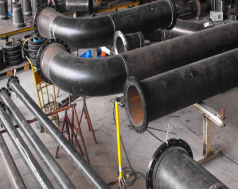
Mechanical tubing refers to tubing used to bear mechanical loads, transmit power, or form mechanical structures—such as drive shafts, hydraulic cylinder barrels, machine tool frame support tubes, bearing sleeves, and ball screw bushings. Its key difference from pressure piping is that mechanical tubing prioritizes mechanical properties, dimensional accuracy, and surface quality, rather than necessarily designing wall thickness based on internal pressure.
This guide explains real-world mechanical tube dimensions, ASTM specifications, tolerance ranges, manufacturing methods, and practical selection advice used by global buyers and engineers.
ASTM A513 covers electric-resistance-welded carbon and alloy steel mechanical tubing. This specification remains widely used in automotive, agricultural, and structural manufacturing.
ASTM A519 Seamless Mechanical Tube
ASTM A519 covers seamless carbon and alloy steel mechanical tubing.
SAE J524 and SAE J525 Tubing
SAE standards are commonly used for hydraulic and transportation systems.
Dimensions – Mechanical and Structural Rounds
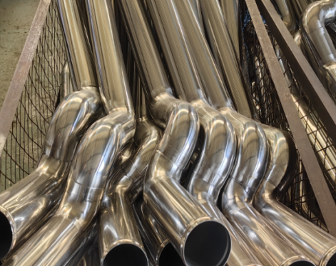
Structural steel pipes: used for mechanical frames, transmission shafts, and supports.
Main standards: GB/T 8162, ASTM A53
Hydraulic/cylinder pipes: used for hydraulic cylinders, cylinder barrels, and precision piston rods
Main standards: GB/T 3639, DIN 2391
Bearing pipes: used for bearing rings and needle bearing jackets
Main standards: GB/T 18254 (special for bearing steel)
High-strength mechanical pipes: used for automotive parts and engineering mechanical arms
Main standards: ASTM A519, EN 10305
2. Classification by production process
Seamless steel pipes: formed by hot rolling or cold drawing, without welds, and strong pressure bearing capacity (such as hydraulic systems).
Welded steel pipes: high-frequency welding or submerged arc welding, low cost, suitable for general structures.
Grade 355 Tube will enhance the benefits of Structural Hollow Sections and then will allow Tubes to compete on an equal footing with other steel sections. Furthermore it will assist Tubular steel in competing with other construction materials.
Chemical Composition – Maximum
Carbon Equivalent – 0.39
Carbon – 0.22
Mn – 1.6
Si – 0.25
Mechanical Properties – Minimum
Yield Strength – 355MPa
UTS – 460MPa
Elongation – 20%
Standard Lengths
Structural and Mechanical tube is stocked in standard lengths of 6 metres, exceptions are:
193.7mm round in thicknesses of 3.5 and 6.0 mm where the stocked lengths are 6.1.
219mm round in a thickness 3.5 mm where the stocked length is 6.1 metres.
219mm round in thicknesses of 4.5 and 6.0mm where the stocked lengths are 6.1 and 9.144 metres.
Selected sizes in the structural tube range are available in 9.144 metre lengths.
Other lengths may be supplied on request, but are subject to minimum order quantities.
Mechanical tubing helps solve these challenges because it offers:
Better concentricity
Improved wall consistency
Enhanced machinability
Smoother internal surfaces
Higher dimensional precision
For example, hydraulic cylinder manufacturers often specify DOM tubing because bore consistency directly impacts seal performance and operating pressure stability.
This guide explains real-world mechanical tube dimensions, ASTM specifications, tolerance ranges, manufacturing methods, and practical selection advice used by global buyers and engineers.
Common Mechanical Tube Standards
ASTM A513 Mechanical TubingASTM A513 covers electric-resistance-welded carbon and alloy steel mechanical tubing. This specification remains widely used in automotive, agricultural, and structural manufacturing.
ASTM A519 Seamless Mechanical Tube
ASTM A519 covers seamless carbon and alloy steel mechanical tubing.
SAE J524 and SAE J525 Tubing
SAE standards are commonly used for hydraulic and transportation systems.
Mechanical Tube Size Chart
| NPS | DN | OD | Thickness WT | |||||
| mm | 10S | kg/m | 40S | kg/m | 80S | kg/m | ||
| 1/4" | 8 | 13.72 | 1.65 | 0.49 | 2.24 | 0.63 | 3.02 | 0.8 |
| 3/8" | 10 | 17.15 | 1.65 | 0.63 | 2.31 | 0.84 | 3.2 | 1.1 |
| 1/2" | 15 | 21.34 | 2.11 | 1 | 2.77 | 1.24 | 3.73 | 1.62 |
| 3/4" | 20 | 26.67 | 2.11 | 1.28 | 2.87 | 1.69 | 3.91 | 2.2 |
| 1" | 25 | 33.4 | 2.77 | 2.09 | 3.38 | 2.5 | 4.55 | 3.24 |
| 1-1/4" | 32 | 42.2 | 2.77 | 2.69 | 3.56 | 3.39 | 4.85 | 4.47 |
| 1-1/2" | 40 | 48.3 | 2.77 | 3.11 | 3.68 | 4.05 | 5.08 | 5.41 |
| 2" | 50 | 60.3 | 2.77 | 3.93 | 3.91 | 5.44 | 5.54 | 7.48 |
| 2-1/2" | 65 | 73 | 3.05 | 5.26 | 5.16 | 8.63 | 7.01 | 11.41 |
| 3" | 80 | 88.9 | 3.05 | 6.46 | 5.49 | 11.29 | 7.62 | 15.27 |
| 3-1/2" | 90 | 101.6 | 3.05 | 7.41 | 5.74 | 13.57 | 8.08 | 18.64 |
| 4" | 100 | 114.3 | 3.05 | 8.37 | 6.02 | 16.08 | 8.56 | 22.32 |
Dimensions – Mechanical and Structural Rounds
| Nominal diameter in mm | Outside diameter in mm | |
| Maximum | Minumum | |
| 21 | 21.7 | 20.9 |
| 25 | 25.5 | 24.7 |
| 27 | 27.3 | 26.5 |
| 32 | 32.2 | 31.4 |
| 34 | 34.1 | 33.3 |
| 38 | 38.4 | 37.6 |
| 42 | 42.8 | 42 |
| 48 | 48.7 | 47.9 |
| 51 | 51.4 | 50.6 |
| 57 | 57.4 | 56.6 |
| 60 | 60.7 | 59.9 |
| 63 | 63.9 | 63.1 |
| 76 | 76.5 | 45.5 |
| 89 | 89.3 | 88.5 |
| 95 | 95.4 | 94.6 |
| 102 | 102 | 101.2 |
| 114 | 114.9 | 113.7 |
| 127 | 127.6 | 126.7 |
| 140 | 140.2 | 139.1 |
| 152 | 153 | 151.8 |
| 165 | 165.7 | 164.5 |
| 178 | 178.4 | 177.2 |
| 193 | 194.3 | 193.1 |
| 219 | 219.5 | 218.5 |
Main types of mechanical steel pipes:
1. Classification by useStructural steel pipes: used for mechanical frames, transmission shafts, and supports.
Main standards: GB/T 8162, ASTM A53
Hydraulic/cylinder pipes: used for hydraulic cylinders, cylinder barrels, and precision piston rods
Main standards: GB/T 3639, DIN 2391
Bearing pipes: used for bearing rings and needle bearing jackets
Main standards: GB/T 18254 (special for bearing steel)
High-strength mechanical pipes: used for automotive parts and engineering mechanical arms
Main standards: ASTM A519, EN 10305
2. Classification by production process
Seamless steel pipes: formed by hot rolling or cold drawing, without welds, and strong pressure bearing capacity (such as hydraulic systems).
Welded steel pipes: high-frequency welding or submerged arc welding, low cost, suitable for general structures.
Material specification
Grade 355 Tubes, also commonly known as Structural Hollow Sections, was launched in February. Previously Grade 300 Tube, launched in June 1997, was available. Engineers can now use an increase minimum yield stress of 355MPa yield and an Ultimate yield tensile stress of 450MPa for designs.Grade 355 Tube will enhance the benefits of Structural Hollow Sections and then will allow Tubes to compete on an equal footing with other steel sections. Furthermore it will assist Tubular steel in competing with other construction materials.
Chemical Composition – Maximum
Carbon Equivalent – 0.39
Carbon – 0.22
Mn – 1.6
Si – 0.25
Mechanical Properties – Minimum
Yield Strength – 355MPa
UTS – 460MPa
Elongation – 20%
Standard Lengths
Structural and Mechanical tube is stocked in standard lengths of 6 metres, exceptions are:
193.7mm round in thicknesses of 3.5 and 6.0 mm where the stocked lengths are 6.1.
219mm round in a thickness 3.5 mm where the stocked length is 6.1 metres.
219mm round in thicknesses of 4.5 and 6.0mm where the stocked lengths are 6.1 and 9.144 metres.
Selected sizes in the structural tube range are available in 9.144 metre lengths.
Other lengths may be supplied on request, but are subject to minimum order quantities.
Mechanical Properties:
| Grade | Condition | MPa Tenslle Point | Yield Point | Elongation |
| 1020 | CW | ≥414 | ≥483 | ≥5% |
| SR | ≥345 | ≥448 | ≥10% | |
| A | ≥193 | ≥331 | ≥30% | |
| N | ≥234 | ≥379 | ≥22% | |
| 1025 | CW | ≥448 | ≥517 | ≥5% |
| SR | ≥379 | ≥483 | ≥8% | |
| A | ≥207 | ≥365 | ≥25% | |
| N | ≥248 | ≥379 | ≥22% | |
| 4130 | SR | ≥586 | ≥724 | ≥10% |
| A | ≥379 | ≥517 | ≥30% | |
| N | ≥414 | ≥621 | ≥20% | |
| 4140 | SR | ≥689 | ≥855 | ≥10% |
| A | ≥414 | ≥552 | ≥25% | |
| N | ≥621 | ≥855 | ≥20% |
Why Mechanical Tube Matters in Industrial Applications ?
Many industrial systems depend on precise fitment and predictable performance. Even small dimensional variations can create assembly issues, vibration problems, or premature wear.Mechanical tubing helps solve these challenges because it offers:
Better concentricity
Improved wall consistency
Enhanced machinability
Smoother internal surfaces
Higher dimensional precision
For example, hydraulic cylinder manufacturers often specify DOM tubing because bore consistency directly impacts seal performance and operating pressure stability.