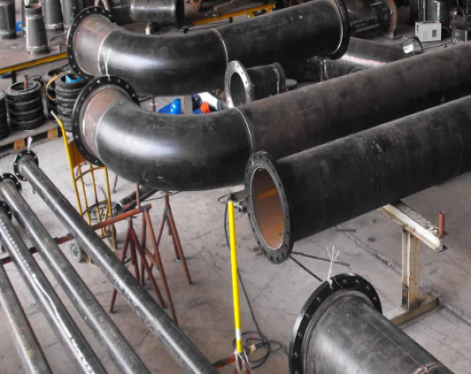
What is OCTG Casing Pipe?
OCTG casing pipe, short for Oil Country Tubular Goods, refers to a category of seamless steel tubular products that include drill pipe, casing pipe , and tubing used in the exploration and production of oil and gas. Among them, casing pipe plays a crucial role in drilling operations — it is installed inside the wellbore to support the borehole wall, prevent collapse, and isolate different geological formations to ensure well integrity.
These pipes are manufactured from high-strength steel grades and are engineered to resist extreme pressure, temperature, and corrosive fluids commonly found in oilfield environments. By providing structural support and protection, OCTG casing pipes form the backbone of safe and efficient drilling and production systems in the modern energy industry.
What are OCTG casing pipe sizes?
The size of OCTG casing pipes is defined by two core parameters: outer diameter (OD) and wall thickness. These dimensions are universally standardized in accordance with American Petroleum Institute (API) specifications—the industry’s authoritative benchmark for oilfield tubular products.
Commercially common OCTG casing sizes span an outer diameter range of 4 1/2 inches to 20 inches, while wall thickness varies dynamically to match distinct well depth and pressure demands: thicker walls suit high-pressure deep wells, whereas thinner profiles apply to shallower, low-pressure scenarios.
A typical sizing specification, for instance, references a “7-inch casing” (denoting a 7.00-inch outer diameter), with its wall thickness further specified either by nominal weight in pounds per foot (lb/ft)—a prent industry convention—or direct measurement in millimeters.
Ultimately, the precise size and technical specifications of OCTG casing are determined by site-specific drilling conditions, well engineering design, and regulatory compliance requirements governing oil and gas operations.

Common API 5CT OCTG casing pipe size chart
How to use the casing pipe size chart?
When selecting casing pipe, engineers must consider:
Well depth and pressure: deeper or high-pressure wells require thicker, heavier casing pipe.
Formation conditions: corrosive environments may need higher-grade materials (e.g., L80, P110).
Compatibility: ensure proper clearance between casing, tubing, and drill string.
Read more: Types of OCTG Pipe
OCTG casing pipe, short for Oil Country Tubular Goods, refers to a category of seamless steel tubular products that include drill pipe, casing pipe , and tubing used in the exploration and production of oil and gas. Among them, casing pipe plays a crucial role in drilling operations — it is installed inside the wellbore to support the borehole wall, prevent collapse, and isolate different geological formations to ensure well integrity.
These pipes are manufactured from high-strength steel grades and are engineered to resist extreme pressure, temperature, and corrosive fluids commonly found in oilfield environments. By providing structural support and protection, OCTG casing pipes form the backbone of safe and efficient drilling and production systems in the modern energy industry.
What are OCTG casing pipe sizes?
The size of OCTG casing pipes is defined by two core parameters: outer diameter (OD) and wall thickness. These dimensions are universally standardized in accordance with American Petroleum Institute (API) specifications—the industry’s authoritative benchmark for oilfield tubular products.
Commercially common OCTG casing sizes span an outer diameter range of 4 1/2 inches to 20 inches, while wall thickness varies dynamically to match distinct well depth and pressure demands: thicker walls suit high-pressure deep wells, whereas thinner profiles apply to shallower, low-pressure scenarios.
A typical sizing specification, for instance, references a “7-inch casing” (denoting a 7.00-inch outer diameter), with its wall thickness further specified either by nominal weight in pounds per foot (lb/ft)—a prent industry convention—or direct measurement in millimeters.
Ultimately, the precise size and technical specifications of OCTG casing are determined by site-specific drilling conditions, well engineering design, and regulatory compliance requirements governing oil and gas operations.
Common API 5CT OCTG casing pipe size chart
| Size Designation | Outer Diameter (OD) | Nominal Weight | Wall Thickness (WT) | Common Steel Grade | Typical Application Scenario |
| 4 ½" Casing | 4.50 in (114.3 mm) | 11.60 lb/ft | 6.35 mm | J55, N80 | Shallow to medium-depth surface casing (500-1500m) |
| 5 ½" Casing | 5.50 in (139.7 mm) | 17.00 lb/ft | 7.72 mm | N80 | Intermediate casing for 2000-3000m wells, isolating formation fluids |
| 5 ½" Casing | 5.50 in (139.7 mm) | 23.00 lb/ft | 10.54 mm | P110 | High-pressure gas well casing, resisting formation collapse |
| 7" Casing | 7.00 in (177.8 mm) | 29.00 lb/ft | 10.36 mm | N80 | Standard production casing for medium-low pressure reservoirs |
| 7" Casing | 7.00 in (177.8 mm) | 38.00 lb/ft | 13.72 mm | P110 | Casing for salt-gypsum layers or complex formations, with enhanced collapse resistance |
| 8 ⅝" Casing | 8.625 in (219.1 mm) | 36.00 lb/ft | 10.16 mm | J55, N80 | Deep surface casing (1500-2500m), building wellhead infrastructure |
| 9 ⅝" Casing | 9.625 in (244.5 mm) | 47.00 lb/ft | 11.99 mm | N80 | Intermediate casing for deep wells, adapting to thick surface formations |
How to use the casing pipe size chart?
When selecting casing pipe, engineers must consider:
Well depth and pressure: deeper or high-pressure wells require thicker, heavier casing pipe.
Formation conditions: corrosive environments may need higher-grade materials (e.g., L80, P110).
Compatibility: ensure proper clearance between casing, tubing, and drill string.
Read more: Types of OCTG Pipe